Keypad Testbench Example
Introduction
In this testbench, we are simulating a 4x4 matrix keypad. The testbench connects rows and columns together through virutal switches and checks whether the DUT (Device Under Test) correctly decodes which key is pressed.
To do this, we introduce several new SystemVerilog constructs:
tranif1genvarandgenerateloopstaskdefinitionspullupprimitives
Definitions
tranif1
The tranif1 primitive is a conditional bidirectional switch.
tranif1 key_switch(rows[r], cols[c], keys[r][c]);When keys[r][c] (control signal) is equal to 1, rows[r] (inout1 signal) and cols[c] (inout2 signal) are shorted together. When control is equal to 0, the switch is open and the two signals are not connected.
genvar and generate
In hardware modeling, we often need to create many repeated structures like the 16 switches of a 4x4 keypad. genvar declares a loop variable for generate-time use. A generate block creates multiple instances of hardware.
    genvar r, c;
    generate
        for (r = 0; r < 4; r++) begin : row_loop
            for (c = 0; c < 4; c++) begin : col_loop
                // when keys[r][c] == 1, connect cols[c] and rows[r]
                tranif1 key_switch(rows[r], cols[c], keys[r][c]);
            end
        end
    endgenerate
The double loop creates 16 conditional switches.
task
A task is a reusable block of simulation code. Unlike functions, tasks can contain delay and event controls (#, @, wait). Tasks are useful for producing stimuli and checking results.
// task to check expected values of d0 (recently pressed key) and d1 (previously pressed key)
    task check_key(input [3:0] exp_d0, exp_d1, string msg);
        #100;
        assert (d0 == exp_d0 && d1 == exp_d1)
            $display("PASSED!: %s -- got d0=%h d1=%h expected d0=%h d1=%h at time %0t.", msg, d0, d1, exp_d0, exp_d1, $time);
        else
            $error("FAILED!: %s -- got d0=%h d1=%h expected d0=%h d1=%h at time %0t.", msg, d0, d1, exp_d0, exp_d1, $time);
        #50;
    endtask
This task waits, compares outputs against expected values, and reports failures.
pullup
In real hardware, pull-up resistors hold signals at a high logic value when nothing is actively driving them. SystemVerilog provides a pullup primitive for modeling this behavior in simulation.
pullup(rows[0]);
pullup(rows[1]);
pullup(rows[2]);
pullup(rows[3]);
Without a pull-up, a floating wire would have high impedance. Pressing a key (closing a tranif1 switch) pulls the row low when the column is driven low.
Testbench Code
Below is an example of a keypad testbench using these constructs for simple stimuli.
`timescale 1 ns/1 ns

module keypad_tb();
    logic           clk;    // system clock
    logic           reset;  // active high reset
    tri     [3:0]   rows;   // 4-bit row input
    tri     [3:0]   cols;   // 4-bit column output
    logic   [3:0]   d0;     // new key
    logic   [3:0]   d1;     // previous key

    // matrix of key presses: keys[row][col]
    logic [3:0][3:0] keys;

    // dut
    keypad dut(.clk(clk), .reset(reset), .rows(rows), .cols(cols), .d0(d0), .d1(d1));

    // ensures rows = 4'b1111 when no key is pressed
    pullup(rows[0]);
    pullup(rows[1]);
    pullup(rows[2]);
    pullup(rows[3]);

    // keypad model using tranif
    genvar r, c;
    generate
        for (r = 0; r < 4; r++) begin : row_loop
            for (c = 0; c < 4; c++) begin : col_loop
                // when keys[r][c] == 1, connect cols[c] <-> rows[r]
                tranif1 key_switch(rows[r], cols[c], keys[r][c]);
            end
        end
    endgenerate

    // generate clock
    always begin
        clk = 0; #5;
        clk = 1; #5;
    end

    // task to check expected values of d0 and d1
    task check_key(input [3:0] exp_d0, exp_d1, string msg);
        #100;
        assert (d0 == exp_d0 && d1 == exp_d1)
            $display("PASSED!: %s -- got d0=%h d1=%h expected d0=%h d1=%h at time %0t.", msg, d0, d1, exp_d0, exp_d1, $time);
        else
            $error("FAILED!: %s -- got d0=%h d1=%h expected d0=%h d1=%h at time %0t.", msg, d0, d1, exp_d0, exp_d1, $time);
        #50;
    endtask

    // apply stimuli and check outputs
    initial begin
        reset = 1;

        // no key pressed
        keys = '{default:0};

        #22 reset = 0;

        // press key at row=1, col=2
        #50 keys[1][2] = 1;
        check_key(4'h6, 4'h0, "First key press");

        // release button
        keys[1][2] = 0;

        // press another key at row=0, col=0
        keys[2][3] = 1;
        check_key(4'hc, 4'h6, "Second key press");

        // release buttons
        #100 keys = '{default:0};

        #100 $stop;
    end

    // add a timeout
    initial begin
        #5000; // wait 5 us
        $error("Simulation did not complete in time.");
        $stop;
    end
endmodule
Waveform Output
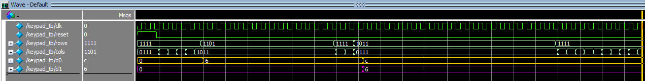
In this simulation waveform, you can see two key presses being applied: on the first press the DUT captures the new key value into d0 (gold) while d1 (purple) stays at 0, and on the second press the old key shifts into d1 while the new value appears in d0, showing the design correctly tracks the current and previous keys. Notice how there are no floating values on the rows bus because of the pull-up resistors.